Introduction
In the life cycle of any structure, tower structure, a sprawling industrial factory, or an offshore structure, the integrity of its structural members is paramount. Over time, various factors can compromise this integrity, leading to a need for strengthening. This blog post explores a practical and efficient method for quickly assessing the need to strengthen a structural member, with a particular focus on steel sections affected by corrosion. I will walk through a process that leverages readily available tools and a methodical comparison of properties and stresses, enabling engineers to make informed decisions about structural remediation. The goal isn’t just to identify a problem, but to quantify it, and ultimately, to pave the way for a targeted strengthening solution. This quick and easy analysis can serve as a vital first step in a more comprehensive structural assessment. I will focus on a scenario where corrosion has degraded the cross-section of a steel tubular member, necessitating an evaluation of its remaining capacity and the potential need for reinforcement.
Reduced Steel Cross-section due to Corrosion
Corrosion is a pervasive enemy of offshore steel structures. It’s a natural electrochemical process that converts refined metal into a more stable form, typically an oxide, hydroxide, or sulphide. For steel, this often manifests as rust, a reddish-brown flaky substance. The insidious nature of corrosion lies in its ability to gradually reduce the effective cross-sectional area of a structural member. This reduction directly diminishes the member’s capacity to resist applied loads, such as axial forces, bending moments, or shear stresses.
When evaluating a corroded steel member, the first critical step is to determine the extent of material loss accurately. Once the remaining thickness and geometry are established, the actual or “reduced” cross-section can be defined. The effective cross-sectional area, moments of inertia, and section moduli of the reduced section will be significantly lower than the original design values, directly impacting the member’s structural performance. This quantifiable reduction in geometric properties forms the basis of our quick analysis, allowing us to compare the compromised member against its original design intent and against a strengthened alternative.
Modelling of Built-up Sections in Idea-Statica
Idea-Statica is a structural analysis software widely used for the design and analysis of steel connections and members. While Idea-Statica is renowned for connection design, its ability to define and analyse arbitrary cross-sections is particularly useful here.
To model a built-up section representing a strengthened member (e.g., an existing corroded beam with welded-on plates), you would typically follow these steps in Idea-Statica https://www.ideastatica.com/:
- Start a new project: Select a “Member” or “General” analysis type, not just a “Connection” project.
- Define cross-section: Instead of selecting a standard hot-rolled section, you would use the “General cross-section editor” or “Built-up cross-section” option.
- Draw the geometry: Use the drawing tools to accurately represent the existing corroded section and the proposed strengthening elements (e.g., cover plates, angles, or channels). You can input precise dimensions and locations of each plate or profile.
- Assign material properties: Ensure the correct steel grade (e.g., S275, S355) is assigned to each part of the built-up section.
- Define welds: If strengthening involves welding, you can model the welds. While the primary focus for this quick analysis isn’t weld design, representing them can help visualize the full built-up section. In the present case study, full penetration welds are assumed.
- Calculate cross-section properties: Once the geometry is defined, Idea-Statica can automatically calculate the key cross-sectional properties, including:
- Area (A)
- Moments of inertia (Ix, Iy)
- Section moduli (Wx, Wy)
- Radius of gyration (rx, ry)
- Shear area (Av)
- Torsional constant (J)
These properties are crucial for our comparative analysis and form the basis for evaluating the member’s resistance to various types of loading.
In the case study presented, the original cross-section was a tubular of Outer Diameter (OD) of 254.0 mm (10 inches) with a Wall Thickness (WT) of 12.7 mm ½ inch) as shown in Figure 1.
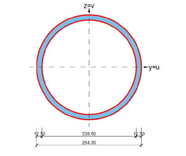
Figure 1: Dimensions of the original Cross-section
Due to severe corrosion, an onsite survey indicated that the new dimensions of the tubular were reduced to an OD of 244.8 mm and WT of 8.1 mm. There was a reduction of 36 % reduction in WT. The solution was to increase the cross-section area which would have resulted in increased section modulus in the Y and Z direction. Since the bending was predominantly in the global Y direction, it was considered appropriate to increase the section modulus in the global Y direction. The built-up section selected is shown in Figure 2.
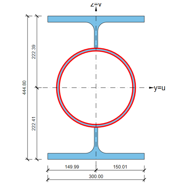
Figure 2: Built-up section, using a cut HEB 300 section
The cut HEB-300 section with dimensions is shown in Figure 3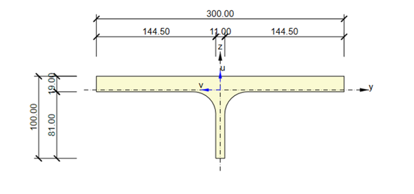
Figure 3: Dimensions of cut HEB 300 section.
Comparing the Cross-section Properties
With the cross-sectional properties for both the original member, the reduced (corroded) member, and the proposed strengthened (built-up) member established, the next crucial step is a direct comparison. This comparison provides a clear quantitative understanding of the impact of corrosion and the effectiveness of the proposed strengthening.
Key properties to compare include:
- Cross-sectional Area (A): This directly relates to axial load resistance. A reduction in area means a higher stress for the same axial force. The strengthened section should ideally have an area greater than or equal to the original.
- Moments of Inertia (Ix, Iy): These are critical for bending resistance and deflection control. A smaller moment of inertia leads to larger deflections and higher bending stresses. The strengthened section must restore or increase these values.
- Section Moduli (Wx, Wy): Directly related to bending stress. σb=M/W. A reduced section modulus means higher bending stress for the same bending moment. This is arguably one of the most important parameters for bending members.
- Radius of Gyration (rx, ry): Important for buckling resistance of compression members. A reduced radius of gyration indicates a lower buckling capacity.
The comparison should ideally be presented in a clear, tabular format, highlighting the percentage reduction in properties due to corrosion and the percentage increase achieved by strengthening. This visual representation immediately conveys the severity of the degradation and the efficacy of the remedial action. Enclosed is an Excel sheet that is free to download.
Excel Sheet Which Compares the Sectional Properties
To streamline and standardize the comparison process, I have included an Excel sheet that you may download. This tool allows for quick input of data, automated calculations, and clear presentation of results.
The enclosed Excel sheet compares the structural properties of the different sections listed below:
-
- Original Section
- Reduced/Corroded Section
- Strengthened/Built-up section properties calculated using Idea-Statica
This Excel sheet becomes a dynamic tool. By simply inputting the new cross-sectional properties, you can instantly see the impact of corrosion and the effectiveness of various strengthening schemes. (Excel sheet to compare cross-sections)
Determine the Class of the Section
Before performing a stress comparison, it is important to determine the “class” of the steel cross-section for all three states: original, corroded, and strengthened. Section classification, as per design codes like Eurocode 3 or AISC, is critical because it dictates the effective capacity of the member and ensures a desirable failure mode, primarily preventing premature local buckling. The aim for most structural members is for them to be Class 1, 2, or 3, as these classes allow the full material strength to be utilized before local buckling occurs.
Steel sections are typically classified based on the slenderness of their component plates (e.g., flange outstands, web panels). This slenderness is a ratio of the plate width to its thickness, compared against limiting values that depend on the steel yield strength (Fy) and a material constant (ϵ=235/Fy)
The four classes are generally defined as:
- Class 1 (Plastic): These sections can form a plastic hinge with sufficient rotation capacity to allow redistribution of moments in a continuous member or frame. They can reach their full plastic moment capacity (Mpl).
- Class 2 (Compact): These sections can reach their full plastic moment capacity (Mpl) but have limited rotation capacity compared to Class 1.
- Class 3 (Semi-compact): These sections can reach their yield moment capacity (My), but local buckling prevents the development of the plastic moment. The design resistance is based on the elastic section modulus (Wel).
- Class 4 (Slender): Local buckling occurs before the yield stress is reached in some part of the cross-section. The design resistance must be based on an effective section modulus, considering the reduced effective area due to local buckling.
For our quick analysis, particularly for members where we want them to yield before local buckling, we are aiming for sections that are Class 1, 2, or 3. If the corroded section falls into Class 4, it immediately flags a significant issue, as its capacity is severely diminished even before yield. Similarly, when designing the strengthened section, it is crucial to ensure the added plates do not create new slender elements that would downgrade the overall section classification to Class 4.
The enclosed Excel sheet will assist you in determining the Class of the cross-section. The critical buckling load can be determined based on the class of the section. I will discuss how this is done in an upcoming Blog post.
Comparison of Stresses
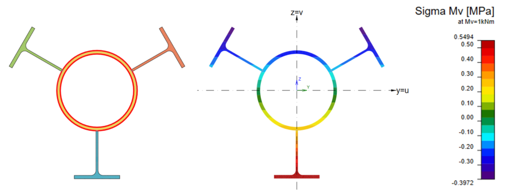
The goal of this quick analysis is to determine if the structural member can safely carry the applied loads, both in its current state and after strengthening. The stresses due to unit Axial, Bending, and Shear are compared. The enclosed report provides the structural properties and stresses for all 3 types of cross-section compared. Some example illustrations for bending in the global Y axis for all 3 conditions are shown in Figure 4, Figure 5, and Figure 6. 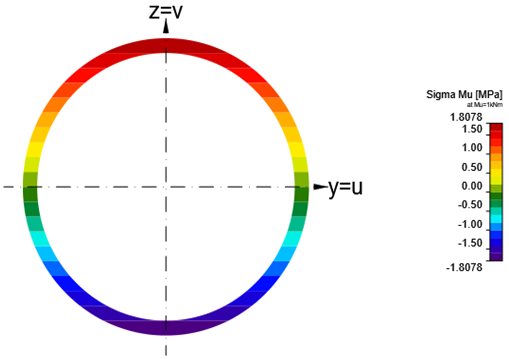
Figure 4: Original Section Bending Stress in the Global y Direction.
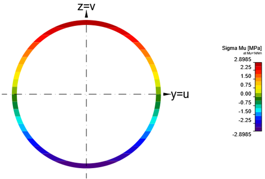
Figure 5: Corroded Section Bending Stress in the Global y Direction
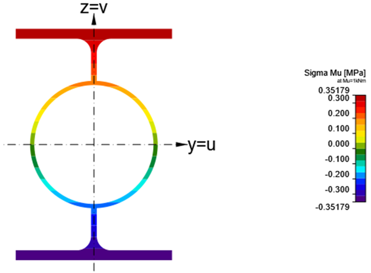
Figure 6: Built-up Section Bending Stress in the Global y Direction
The change in strength capacity can then be quantified. The actual stresses can be calculated by scaling the unit stresses by the actual axial load, bending moment, and shear force. Readers who would like to get further details may download the enclosed report.
Conclusion and Summary
The ability to perform a quick and easy structural analysis is an invaluable skill for any engineer tasked with maintaining the integrity of existing structures. As demonstrated, a methodical approach, particularly when dealing with issues like corrosion, can provide rapid insights into the structural health of a member and the efficacy of potential strengthening solutions.
We began by emphasizing the importance of accurately quantifying the extent of material loss due to corrosion, which directly impacts the member’s reduced cross-sectional properties. The subsequent use of tools like Idea-Statica allows for precise modelling of built-up, strengthened sections, providing their critical geometric properties. The power of a well-structured Excel sheet then comes into play, enabling a direct and transparent comparison of these properties across the original, corroded, and strengthened states. Finally, by comparing the actual stresses under design loads against allowable limits for all three scenarios, we can definitively ascertain the need for strengthening and validate the proposed solution.
This quick and easy structural analysis provides a robust framework for initial assessment. It allows engineers to:
- Rapidly identify critical members that are no longer performing to their original design capacity.
- Quantify the severity of degradation and its impact on structural performance.
- Evaluate different strengthening options quickly and efficiently without resorting to complex, time-consuming full-scale analyses at the outset.
- Make informed decisions about the necessity and scope of strengthening works, ultimately ensuring the safety and longevity of the structure.
While this approach offers a streamlined method for initial assessment, it’s crucial to remember that it serves as a preliminary evaluation. Any significant strengthening project will ultimately require a more detailed and comprehensive analysis, adhering to relevant building codes and standards. However, this quick and easy analysis provides the essential first step, guiding the decision-making process and laying the groundwork for a safe and effective structural intervention.
Attachments
Excel sheet to compare cross-section properties
Excel sheet to determine the Class of a cross-section as per Eurocode
Full report on cross-section and stress analysis report
Software
Disclaimer
This blog post is for information purposes. All terms and conditions stated in the disclaimer page shall apply.