Introduction
This article will show you how to design a glass hemispherical geodesic dome. In a previous article I wrote The Air in Geometry: Design of Geodesic Domes I wrote about Geodesic Domes and their geometric properties. I have expanded on this topic and demonstrated how to design a large geodesic dome (of 10 m diameter) using glass and aluminum. The project provides a step-by-step approach for the design of a Geodesic Dome listed below:
- Specifications of a hemispherical dome
- Eurocodes used for the design of the Aluminum Frame and Glass Panels
- Section and Material Definition
- Wind Simulations and Other Loads
- Stress Analysis of the Aluminum Frame and Glass Panels
- Code check for Aluminum and Glass Panels
Design Codes
The basic standard group used is the EN 1991 with the national Annex CEN | 2015-09. The design of Aluminum structures is performed as per EN 1999 with national Annex CEN | 2013-12. The glass design is as per DIN 18008 Edition DIN 18008-2020-05.
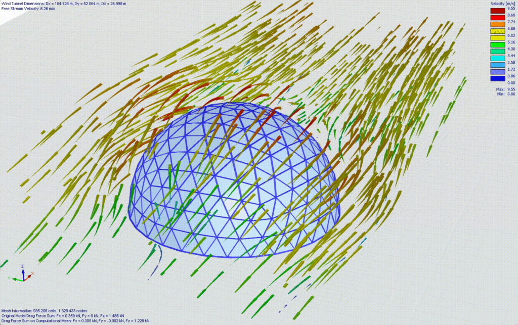
Windloads Using Computational Fluid Dynamics (CFD)
An advanced Computational Fluid Dynamics (CFD) is used to simulate the wind pressure on the glass dome. Wind loads on a curved structure are difficult to model because, as the wind profile moves along a curved surface, the direction vectors of wind velocity change. CFD models the wind pressures more accurately than traditional means.
Below are some animations showing the velocity streams as they go around the Geodesic Dome

Velocity Streamlines
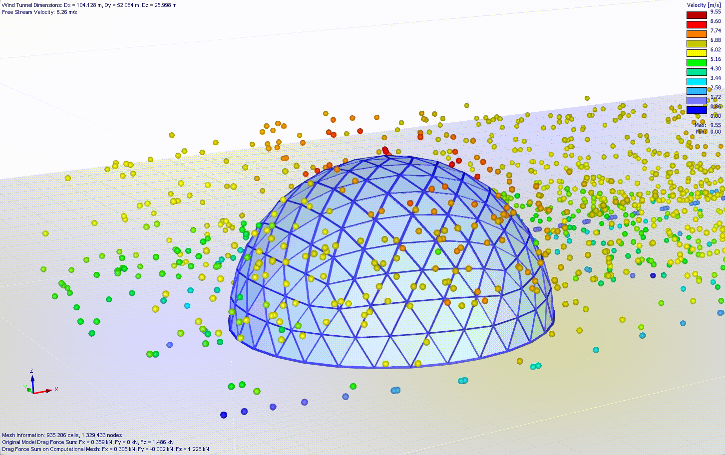
Velocity of wind represented by particles.
The analysis is performed using RFEM-6 with the respective addons for Aluminium and Glass Design. The wind simulation is performed in RWIND-3.
The full report is enclosed with this blogpost (Full Report).